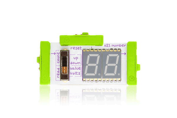
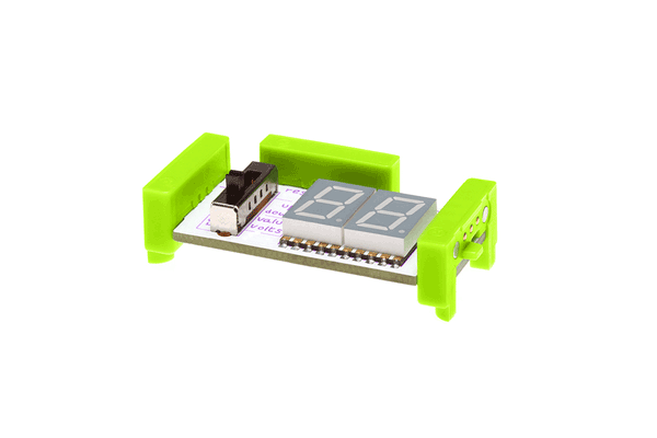
The number module displays information about the signal it’s receiving from your other modules. It features a two-digit, seven-segment LED display. In the “read” mode, the module displays information about the signal it’s receiving. In the “count” mode, the module counts up or down with each trigger. The counter can be reset by receiving a trigger at the reset bitSnap.
Geek Speak
This updated number module has 2 main modes and 2 settings under each mode. Use the 4-position switch to choose between the modes.
READ MODE: Read mode has two settings: values and volts. The number module reads the voltage on the input bitsnap, then calculates and displays either a value between 00-99 or a voltage between 0.0 - 5.0. The voltage on the output bitsnap is a filtered PWM value that equals the voltage on the input bitsnap.
COUNT MODE: Count mode has two settings: up (from 00-99) and down (from 99-00). A step to the next number happens on input low-to-high transitions. The voltage on the output bitsnap is a filtered PWM value that is proportional to the number on display. For example, if the displayed number is 50 then the output voltage is 50% of 5V, or 2.5V. The RESET bitsnap can be used in this mode to reset the number on display. In the "up" setting, the display resets to "00". In the "down" setting, the display resets to "99". The RESET bitsnap resets the number on low-to-high transitions.
Under the Hood
An Atmega168 is used to constantly read the signal from the switch and determine which mode the module is in. It also reads the buffered signal from the input bitsnap, and sends a PWM signal through a Sallen key filter to the output bitsnap. In "read" mode, the signal from the input bitsnap is passed from the ADC pin to the PWM output. In "count" mode, a step to a new number is triggered on a low-to-high pin-change interrupt on the ADC pin. A PWM lookup table is used to output the corresponding PWM value. The reset is also triggered on a low-to-high transition. The Atmega168 also controls the seven-segment LED display to display the correct value.
More from littleBits!


